


Page 27 - SPEMD_62-3
P. 27
rev port estomatol med dent cir maxilofac . 2021;62(3):150-156         153


           dried with an oil -free airstream to obtain a clean surface, thus   structions. The RMGI was hand -mixed for 10 seconds until a
           preventing contamination.                           homogeneous mixture was obtained. A uniform layer of ce-
              Group 1 crowns were luted with dual -cure self -adhesive   ment was placed on the crown’s inner surface using the spat-
                                  ™
           resin cement (G -CEM LinkAce , GC Corporation, Tokyo, Japan;   ula. The seating protocol was the same as in group 1. Excess
           Lot 180611B; Val: 07/2020) according to the manufacturer’s in-  cement was removed with the straight explorer as soon as the
           structions. The self -adhesive resin cement was dispensed ho-  cement achieved a rubbery consistency. The manufacturer’s
           mogeneously using a self -mixing syringe. A uniform layer of   recommended setting time of 4.5 minutes was applied. In the
           cement was placed on the crown’s inner surface with a spat-  end, the remaining excesses were cleaned up as necessary.
           ula (Heidemann Spatula n.º 3 TD4173, Dental Market, Lucca,   The processes of placing the die and crown set on the put-
           Italy). The crown was seated onto the die with finger pressure   ty base, carrying out the fracture resistance test, removing the
           and then with a 5 -kg weight, equivalent to a 49 -N seating pres-  remaining crown fragments and cement from the die, and re-
           sure, for 1 minute. 19  During cementation, each surface was   peating the procedure for all crowns were executed in the
                                        ®
           light -cured for 1 second (Bluephase  Style 20i, Ivoclar Viva-  same way as for group 1. A single operator carried out the
           dent, Schaan, Liechtenstein), and then the excess cement was   cementation of all crowns.
           removed with a straight explorer (Explorers No. 6 TD4006, Den-  The sample size (n=20) was selected based on the study of
           tal Market, Lucca, Italy). Each surface was light -cured again for   Sorrentino et al., who tested the fracture resistance of Cer-
                                                                                                            ™
                                                                    ™
           20 seconds each, with the device directed to the interface be-  asmart  full -contour crowns (predecessor of Cerasmart270 ),
                                                                                                             20
           tween the crown and the die to improve marginal integrity. In   using a sample of ten specimens per experimental group.
           the end, all excesses were cleaned up as necessary.  The statistical power of the present study was 93%, with a
              After cementation, the die and crown set was placed in a   significance level of 0.05.
           circumferential putty base (Turboflex Putty Soft Normal Set,   The data were analyzed using IBM SPSS Statistics, version
           R&S, France; Lot 286323; Val: 11/2020) with a 50 -mm diameter   25.0 (SPSS Inc., Chicago, Illinois, USA). Since the Shapiro -Wilk
           and 5 -mm thickness and fixed to the load frame base of the   and Levene’s tests revealed normality and homogeneity
           testing machine. The fracture resistance test was performed   (p>0.05), respectively, the data were analyzed with a paramet-
           in a universal testing machine (Instron, model 4502, Instron   ric Student’s t -test. A statistical significance of α=0.05 was
           Ltd, Bucks, England) with a 5000 -N load cell and a 6 -mm stain-  considered.
           less steel spherical tip at a crosshead speed of 1 mm/minute.
           The set was positioned so that the spherical tip was at the
           center of the crown’s occlusal surface. Then, vertical load was   Results
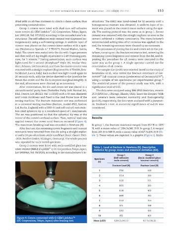
           applied toward the crown until fracture occurred (Figure 4).
           The maximum breaking load was recorded in Newtons (N).  In group 1, the fracture resistance ranged from 852 N to 1855
              After fracture, the remaining crown fragments and cement   N, with a mean value of 1284.3±340.19 N. In group 2, it ranged
           remnants were removed from the die using a straight explor-  from 285 N to 648 N, with a mean value of 417.9±106.35 N (Ta-
           er and a 50 -µm aluminum oxide sandblast (Basic classic 2945-  ble 1). These values are depicted in a graphic (Figure 5). Statis-
           -2026, Renfert GmbH, Hilzingen, Germany). The whole process
           was repeated for each tested specimen.
              Group 2 crowns were luted with resin -modified glass ion-  Table 1. Load at fracture in Newtons (N). Descriptive
           omer cement (RMGI) (FujiCEM  2, GC Corporation, Tokyo, Japan;   statistics by group: mean and standard deviation (SD).
                                  ™
           Lot 180804A; Val: 08/2020), according to the manufacturer’s in-
                                                                               Group 1            Group 2
                                                                             (Self ‑adhesive    (Resin modified glass
                                                                Specimen
                                                                   (n)       resin cement)     ionomer cement)
                                                                            Fracture Load (N)  Fracture Load (N)
                                                                   1             1786               648

                                                                   2             1314               369
                                                                   3             1120               551
                                                                   4             1855               285
                                                                   5             1138               402
                                                                   6             1489               341
                                                                   7             1153               354
                                                                   8             874                398
                                                                   9             1262               430
                                                                   10            852                401
            Figure 4. Crown cemented with G -CEM LinkAce™
            (GC Corporation, Tokyo, Japan) after loading test.  Mean (±SD)   1284.3±340.19       417.9±106.35

