Page 37 - SPEMD_58-2
P. 37
rev port estomatol med dent cir maxilofac . 2017;58(2):91-96 93
the healing abutment. The null hypothesis was that there
would be no difference between interventions.
Materials and methods
®
Sixty rough surface implants (Shot Blasting : alumina parti-
cle sandblasting and acid passivation) screw-shaped implants
®
(Essential Cone, Klockner Implant System, Barcelona, Spain)
were used. The implants belonged to one of the following
groups:
Group A: 30 standard implants. These are an internal
connection, double-threaded implants, characterized by
an atraumatic apex and a progressive core.
Group B: 30 prototype implants. These are the same as
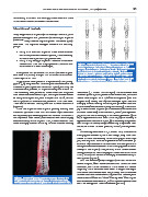
the standard ones, but the progressive core is 0.2 mm Figure 2. Scheme of the Smartpeg screwed to the implant
wider and the threads are sharper. and to the healing abutment. When the Smartpeg is
screwed to the healing abutment, the tip of the transducer
is 1.8mm further from the bone than the tip of the
All implants had a diameter of 3.5 mm (diameter at plat- Smartpeg screwed directly to the implant. (UP: Standard
form level is 4.5 mm), a length of 8 mm and a mechanized implants; BELOW: Prototype implants. From the right to
collar height of 1.5 mm. the left transducer is screwed directly to the implant; and
The implants were placed in 4 bovine ribs (bone quality to the healing abutments of 2, 3.5 and 5 mm of height).
19
type II ), by a experienced clinician (user and knower of the
Klockner Implant System for more than 2 years), following the
manufacturers protocol. 15 implants were place in each rib.
The osteotomy was performed under abundant irrigation abutments (2, 3.5 and 5 mm of height). The transducers were
with sterile saline solution 800 rpm. The implants were insert- screwed by the specific plastic hand-screwdriver. The abut-
2
2
ed using the surgical unit, with a torque of 30 N/cm , so that ments were torqued to 10 N/cm on the implants (with the
the rough/smooth interface was placed at bone crest level. surgical unit). Finally, the ISQ was measured again over the
The distance between the implants had to be at least 4 mm Smartpeg screwed directly to the implant (to assess the influ-
(Figure 1). ence of screw/unscrew over the implant stability). One Smart-
Once the implants were in place, primary stability was peg is used for each implant (so 5 measurements were made
measured by means of RFA with the Osstell ISQ in five differ- with each transducer). In each situation, the ISQ was registered
ent situations, by a second experienced clinician in the use of perpendicular to the Smartpeg in 4 different positions: (1) the
the ISQ device. First, the ISQ was measured over the Smartpeg ISQ is registered from the front of the rib; (2) the stability is
screwed directly to the implant. Then, it was measured over registered from the back of the rib, (3) the stability is registered
three Smartpeg screwed to the top of three different healing from the right of the rib; and (4) the stability is registered from
the left of the rib. At each position, the ISQ was registered
once.
The healing abutments of 2, 3.5 and 5 mm, in which the
Smartpeg are screwed to, are a new design. They have been
created to allow the screwing of the Smartpeg in their inner
part, so it is placed as close as possible to the bone level (to
allow the ISQ measures to be made from a similar point as if
the registration were assessed if the Smartpeg were screwed
directly to the implant). Despite this, in the three different
healing abutments, the Smartpeg is located further from the
bone (1.8 mm) than when the Smartpeg is screwed directly to
the implants (Figure 2).
SPSS 19.0 software (SPSS, Chicago, IL) was used for the sta-
tistical analysis. Mean values and standard deviations were
calculated. The normal distribution of the values and the ho-
mogeneity of the variances were tested through a Kolmogor-
ov-Smirnov and Levene tests, respectively. The differences
between the mean values were compared with the non-para-
Figure 1. Fifteen implants place in each rib, so that the metric Kruskal-Wallis and Mann-Whitney tests. When signif-
rough/smooth interface was placed at bone crest level. icant differences were obtained, 95% confidence intervals were
The distance between the implants had to be at least 4 mm.
found for average and mean differences (p < 0.05).